The 1W FM PLL Transmitter Kit was ordered by phone, from the UK, direct from Broadcast Warehouse. It cost Ł57.95, including UK postage, and arrived promptly by recorded delivery. Four pages of instructions were provided. These were:
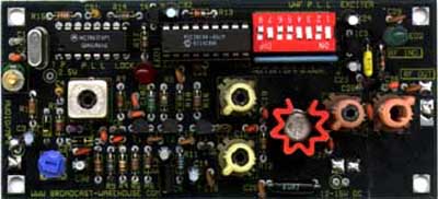
The double sided printed circuit board had a component placement silk screen on the top side, and top and bottom solder resists which assist in making good solder joints.
No schematic was supplied, which was irritating. In my view a schematic is an essential diagnostic tool to trouble-shoot any piece of electronic equipment. Broadcast Warehouse are being unnecessarily paranoid in not providing one. If someone is going to copy their design, they are going to copy it, regardless whether they supply a schematic or not. The fact that they use a one time programmable micro-controller to program the synth chip should deter most casual efforts to copy the design.
In this case, it was easy to draw a schematic from the layout.
The transmitter uses the standard PLL architecture.
The voltage controlled oscillator (VCO) is based on a Fairchild MPSH10 NPN bipolar transistor and operates at half the output frequency. The centre frequency of the VCO is set by an adjustable inductor, which forms a tank circuit with two BB809 varicap diodes. The first varicap is used as the audio modulator, the second is connected to the output of the PLL loop filter. This feedback path enables the output frequency to be locked to the frequency of a stable crystal reference oscillator. The audio input circuit is totally passive. No pre-emphasis is provided, as this unit is designed to be used with a stereo encoder. A small 9V voltage regulator provides a stabilised supply for the VCO and the dc bias for the audio modulating varicap diode.
The output of the VCO is connected to buffer stage based on a MPSH10. At the output of the buffer, sample of the signal is passed to the fin input of the synthesiser IC. Next is the doubler stage, also using a MPSH10. The output network of this stage is tuned using two variable inductors to pick off the second harmonic of the input signal. The output device is a trusty old 2N4427 operating in class C. Two more adjustable inductors in its' output network are provided for output tuning. The output matching network incorporates the harmonic filter. The 2N4427 is provided with a push-on aluminium heatsink. No output socket is provided, so a piece of co-axial cable must be soldered to the PCB. A capacitive sniff is taken from the output to a simple rectifier circuit which drives an on-board LED. This allows the circuit to be tuned without additional test-equipment, (apart from a dummy load) by adjusting the adjustable inductors for maximum LED brightness.
The PLL is implemented with the popular Motorola MC145170 PLL frequency synthesiser IC (MC145170 data sheet (PDF format) - 382K). This synth chip has a three wire serial interface, consisting of data in, clock and enable. The frequency reference comes from a 8MHz crystal, trimmed by a variable capacitor. The synth chip drives an on board lock detect LED via a ZTX300 transistor. The loop reference signal is 50KHz.
The synth chip is programmed by a Microchip Technology PIC16C54 8 bit microcontroller, running off its' internal clock. This chip is one time programmable, and presumably runs code written by Broadcast Warehouse. Programming information is derived from a 8 way DIL switch. This allows the frequency to be set in 100KHz steps, starting from 87.5MHz. The synth is programmed on power-up and whenever one of the DIL switches is altered.
Another small voltage regulator provides a stabilised 5V supply to the synth and micro-controller chips.
The kit I received had two extra components, a resistor and a capacitor. The ICs were supplied loose in the polythene bag with the rest of the components. Although there is a tendency amongst some to go over the top on ESD (electrostatic discharge) precautions, both the ICs are CMOS and therefore potentially susceptible to static damage. A bit of anti-static packaging would have been preferable. No veropins where supplied, which was a minus point, but a plastic trimming tool to fit the variable inductors was - a plus point. The values printed on the ceramic capacitors were extremely faint, needing a magnifying glass to read. The supplied axial 100n capacitors didn't fit very well onto the board. The extra 6.8pf harmonic improvement capacitor is best fitted to the underside of the board, a point which isn't made in the text. There are a couple of mistakes on the PCB silkscreen, which are corrected in the supplied text. The net result of these various issues to keep the constructor on his/her toes. The circuit took one hour and 40 minutes to build, and worked first time.
The DIP switches were set for mid-band, 98MHz. The VCO variable inductor was set to roughly half-way, as indicated in the supplied text. With some adjustment of the remaining variable inductors, the lock LED lit, and the unit tuned for max output power, as indicated by a combination of a amateur radio VSWR meter and the on-board power LED. Having tuned up the unit with a minimum of test equipment, it was then measured with an accurate power meter and spectrum analyser.
The output power of the unit was checked at three different frequencies. At each the frequency, the unit was retuned for maximum power using the on-board power LED. Maximum brightness of the on-board LED corresponded closely to the maximum power as indicated by a power meter
Getting the unit tuned back in again properly after a big frequency change could be a little tricky. It's easy to get "lost", when both the power and lock LEDs are unlit, and no output power is present. The way to avoid this is, having got the unit going at one frequency (probably easiest to start mid-band), alter the frequency in 2MHz steps, and readjust the inductors to maximise the output power between each frequency step. The table below shows it is possible to get 1W of output power across the FM broadcast frequency band with a 13V supply.
| Frequency (MHz) |
Supply Current (mA) | Output Power (W) |
| 88 | 177 | 1.10 |
| 98 | 181 | 1.01 |
| 108 | 191 | 1.07 |
At 13V, 1W output power, the temperature of the output transistor stayed at an acceptable level.
There a test-point (labelled "T.P.") on the PCB silkscreen. This has the output voltage of the PLL loop filter on it. No mention is made of this in the supplied text, which is a pity, as it is an extremely useful diagnostic tool for trouble-shooting PLLs. Under normal circumstances, the voltage on this test-point should be between 0.8V and 4V. Outside this range, the loop will not reliably lock. For maximum loop ruggedness (freedom from losing lock due to temperature, ageing and loading variations), and shortest loop lock times, this test voltage should be in the centre of this range, say between 2.0 and 2.5V. Having chosen your frequency and locked the loop, it's worth monitoring the voltage on the test-point and adjusting the core of the VCO tank coil (L1) to bring the voltage into this range. I found on my unit that when operating at 108MHz, the test-point voltage was around 3.6V even with the ferrite core removed from L1. With the loop operating at this point, the act of applying a DMM to the test-point was enough to knock it off lock. By swapping the ferrite core with an aluminium one (historically available from Cirkit), I was available to bring the TP volts down to 2V. This is because screwing in an aluminium core reduces the inductance of the inductor, whereas introducing a ferrite core increases the inductance.
The frequency was set to 98.000MHz, and the supply voltage was increased to 15V. The table below shows the supply current and output power as the supply voltage was reduced from 15V.
| Supply Voltage (Volts) |
Supply Current (mA) | Output Power (mW) |
| 15 | 208 | 1330 |
| 14 | 196 | 1180 |
| 13 | 181 | 1010 |
| 12 | 165 | 824 |
| 11 | 147 | 648 |
| 10 | 125 | 465 |
| 9 | 95 | 269 |
| 8 | 29 | 0 |
The unit lost lock at 8V, when the output power collapsed to zero. The efficiency of this unit is very good, especially for a 1W output power unit. If you take off the 29mA consumed by the logic and regulators, the DC to RF efficiency of the RF stages at 13V is 50%. With this level of current drain, and the fact that the unit has on board regulators, battery operation is possible.
At 13V supply, 1.00W nominal output power, the harmonics were measured on a spectrum analyser at 88, 98 and 108MHz centre frequencies.
|
Plot of
Spectral Purity, 98MHz 1W, 500MHz span
|
Plot of Spectral Purity, 98MHz 1W, 200MHz span | Plot of
Spectral Purity, 98MHz 1W, 4MHz span
|
|||||||||||||||||||||||||||||||
This unit was supplied with a 6.8pf ceramic capacitor, fitted in parallel with the final output matching inductor. This modification is apparently in response to complaints of poor harmonic rejection. As can be seen from the table and the spectrum analyser plots, the harmonics and sub-harmonic are well within their specified level of -40dB, with the exception noted in the next paragraph. As far as spurious outputs are concerned, the most significant component is a pair of 1MHz sidebands, which can be seen in the 4MHz span plot. These are at -72dBc, slightly better than the specified -70dBc. Similar power sidebands could also be seen at 2MHz and 8MHz offsets from the carrier.
* The 2f figure at 88MHz could be varied from -29dBc (L5 core screwed right out) to -50dBc (L5 core screwed right in). At this frequency, the tuning of L5 results in very little variation in output power. I did the tuning "blind" on the unit, just using the on-board aids, as this is what most people will do, not having access to a spectrum analyser. Having tuned the unit this way, I measured it properly to see what I had got. The point is, if you just tune to for maximum output power, you could leave L5 in a position where the second harmonic level is tending towards unacceptability. Unless you have read this review. This is the problem of using your output match as part of your harmonic filter, rather than a dedicated fixed value low pass filter.
In response to this review, Broadcast Warehouse have stated that the f/2 and 3f/2 products can be reduced to better than -70dBc by careful adjustment of the doubling coils.
This proviso in mind, with this units 1W maximum output power, these levels of harmonics will not cause any problems.
With the unit components as supplied, the output frequency was a minimum of 2.5KHz high. Adding a 33pF ceramic capacitor in parallel with Vc, the reference crystal trimming capacitor, allowed the offset to be adjusted to zero. The capacitor was fitted onto the underside of the PCB. This problem was identified in the Martin Spencer review.
Due to the small output power capability of the unit, coupled with the low supply voltage, bad VSWRs are unlikely to damage this unit. Audio response was not measured, due to the simplicity of the audio part of the circuit. Martin Spencer measured it in his review. By ear it sounded fine, with no hums or whistles.
Why did I choose to review the Broadcast Warehouse unit rather than the Veronica unit? I haven't seen the Veronica unit in the flesh, but I have seen its' picture and schematic. I went for the Broadcast Warehouse unit because it was cheaper, smaller, and uses less components. The Veronica unit uses a PLL based on a 4060 IC, and a divider chain built from 74ALS and LS series logic. The total IC and transistor count for the Veronica unit is 8 and 11, compared to 4 and 5 respectively for the Broadcast Warehouse unit. Less components means less things to go wrong, and less chance to make a mistake in construction. Less logic chips mean less chance of interference from noisy logic lines.
Someone else's review of the Veronica 1 Watt PLL at http://www.geocities.com/Area51/Nebula/3736/veronica_1_watt_pll.review.txt (from archive.org)
A high quality unit, good value for money and reasonably clear assembly instructions. Modern design with low component count. Good technical specification. Tuning takes a little bit of getting used to, easier to set the centre frequency of the VCO if you make use of the test point as detailed above. Few little niggles to fix next time they iterate the PCB. They really ought to supply a schematic. Contact Broadcast Warehouse, info@broadcastwarehouse.com
Martin
Spencers' review of the Broadcast Warehouse 1W PLL
Broadcast
Warehouses' response to Martin Spencers' review of their 1W PLL
[ How to be a Community Radio Station Home Page | Introduction to Community Radio Station Electronics ]