 Scaling the Aerial to your Transmit Frequency
This is a vertically polarised omnidirectional free space aerial (antenna) for 3 metres (FM broadcast band, 88 - 108MHz). It can be scaled for Band I or UHF use. Key features are
This design has been tested with 100W of transmit power. No problems are anticipated for powers up to 500W. The name Slim Jim comes from its slender construction and the use of a J type matching stub (J integrated match = JIM). The integrated balun means that the balanced dipole of the aerial is properly connected to the unbalanced co-axial feeder cable from the transmitter. If you don't use a balun, (for example if you connect your coax straight to a simple dipole), your coax turns into part of your aerial. This is bad as
Why is the Slim Jim so much more efficient than the popular 5/8λ or other ground plane aerials, despite the latter's claimed 3dB gain over a dipole? The Slim Jim vertical angle of radiation is almost parallel to ground so maximum radiation is where it is needed, straight out and all around. With all ground planes, including those with radials even one wavelength long, the vertical angle radiation is tilted upwards at an angle of 30° or more.
*White PVC has been demonstrated to have significantly lower RF losses than grey or black PVC.
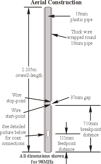
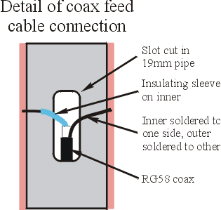
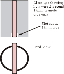
The aerial is constructed from two pieces of plastic plumbing pipe. The inner 19mm diameter pipe supports the wire that goes to make the dipole, This assembly is slid inside the outer 40mm diameter pipe which forms a weatherproof enclosure.
 Scaling the Aerial to your Transmit Frequency
The reference length of the aerial for 98MHz is 2.205m (86.8 inches for Americans and other backwoods dwellers). You will need to scale this figure for your transmit frequency. If, for example, your transmit frequency is 88MHz, take 2.205, divide it by 88 and then multiply by the reference 98 to give 2.456m (96.68 inches). If your transmit frequency is 108MHz, divide 2.205 by 108, and multiply by reference 98 to give 2.000m (78.77 inches). This dimension is your overall-length.
You will also need to calculate the two other distances using the same technique.
Having calculated your dimensions,


You're now ready to start tuning. To do this you will almost certainly need to be
outside (unless you live in an aircraft hanger) and not too close to any building and
trees. Having said this you need to have access to mains power to run your
transmitter and your soldering iron. I used to manage it in my back garden, by
clamping the aerial to the top of a step ladder. The tuning should be done with the
aerial fitted into its' weather-proof sleeve, so push it in. Don't try and fit the
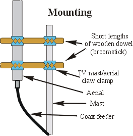
lower end cap at this point. Clamp the aerial upright as shown in the picture.
Connect the full length of your feeder, with
appropriate connectors on each end, one end to your aerial, the other to your VSWR meter. The VSWR meter is connected to your
transmitter with another short piece of cable.
Remember when you're tuning the aerial you will be transmitting, so all usual precautions should be taken. You don't need to transmit at full power, so if you can, turn down the power of your TX, or use a lower power one. The VSWR of the aerial is not affected by the transmitter power. You just need enough power get a sensible reading out of your VSWR meter. This should be in the range of 1 to 5W. It's also worth pointing out that you don't need to run any audio to tune the aerial, furthermore, you don't even have to have your stereo encoder running. All you require is an RF carrier.
To tune the aerial run some power into the aerial, and measure the VSWR. Switch off, and adjust by sliding the feed points up or down together on the thick wires to find the point of minimum VSWR. This corresponds to maximum transmitted power. You will probably need to do this several times to find the best point. A VSWR of better than 1.5 to 1 should be possible. A lossy feed cable will make the VSWR of the aerial look better than it is. Remember the tuning must be done with the aerial upright, and the weatherproof cover fitted. The optimum point should be within 20mm (0.8") of where you started. When you are happy you have found the best point, solder the feed wires on securely. Finally push the lower end cap into the outer sleeve using heat to soften as before. It is possible to get the cap off again using the same technique.
Remember, the more height the better. Read up on siting. If rain is expected, or for semi-permanent installations, wrap some self amalgamating tape (available from Maplin), round the junction between the feeder plug and the socket on the aerial, to keep moisture out. Also wrap tape round junction of feeder cable on feeder plug to stop moisture getting into the cable.
This aerial is based on the "Slim Jim" aerial in the "Two-metre Antenna Handbook" by F C Judd G2BCX, published by Newnes Technical Books, ISBN 0 408 00402 9, now out of print.
[ How to be a Community Radio Station Home Page | Introduction to Community Radio Station Electronics ]
Last updated 25 August 2003